|
|
|
|
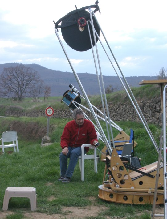
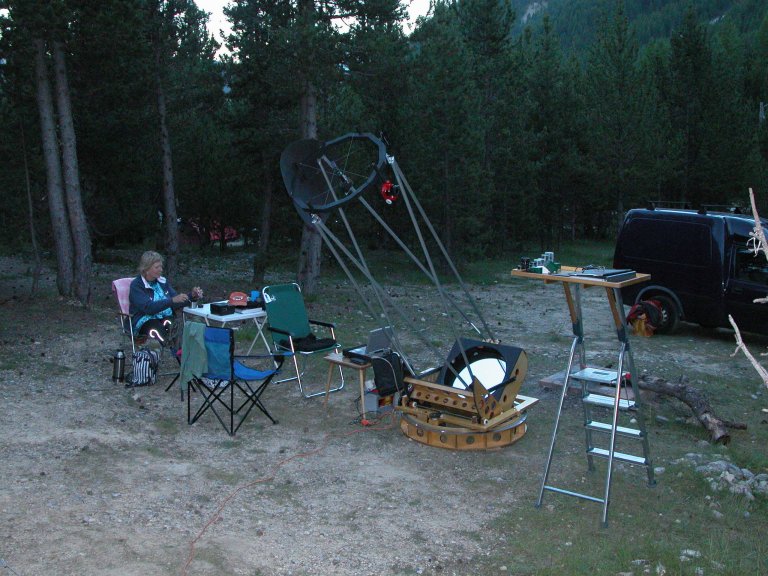
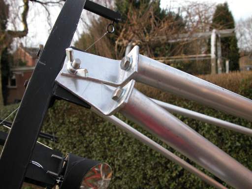
My finished 20" f/5 trilateral Dobsonian telescope in the French 'Provence', April 2008. Behind me, my girlfriend's 12 inch Dob. The first iteration of my computerized tridob didn't keep collimation, so I had to re-design. I made a new wire spider twice (see below). I also changed the position of the trusses, making it still more like the original Mel Bartels design. It keeps its collimation well now and the balance is good! Another picture of this telescope, taken on a dark camping site in Brunissard (Southern France, summer 2008), were my girlfriend Marijke and me are waiting for the dark, is here. The trusses are connected to the mirrorbox with wooden splitblocks. How they are connected to the secondary ring is shown here. I made threaded inserts from delrin, to connect the upper truss connectors to the trusses. |
|
|
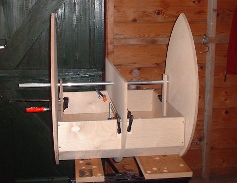
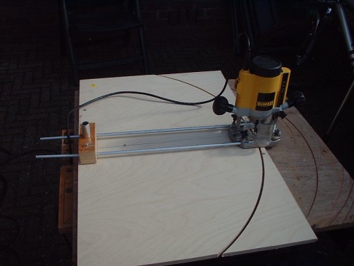
When I started making my trilateral dob I wondered how I could make a jig to attach the three altitude bearings to the mirrorbox, without ending up with three different axes. The result of my thinking is on this page. A front view of the mirrorbox and jig is above. Making the jig is quite simpel: just a length 20 mm diameter aluminium tubing and two pieces of wood. I also used a piece of this 20 mm tubing as a pin for my router jig (as shown here), because when I use a screw or a nail or something and I make the hole larger to be able to get the tubing through it, I am sure I will end up with three different axes. Using the 20 mm tubing in the router jig resulted in perfectly centered bearings around one axis.
How to proceed? First, attach the center bearing to the mirrorbox. Then slide the aluminium tubing through the hole at the calculated COG (18.1" for my scope) and fasten it with two pieces of wood to the sides of the mirrorbox, in the correct position. After that, slide the side bearings on the tubing. The only degree of freedom now is the revolution of the bearings around the aluminium tubing. Fix the bearings into the correct position with clamps and drill the hole for attaching the side bearings to the mirrorbox, or mark the exact position with a pencil, take the side bearings off and remove the surplus wood. The surplus wood of the center bearing can be easily removed without disassembling this bearing, with a small handsaw. This jig keeps the bearings concentric and unable to move up/down and forward/backward. You will still have to do some carefull measurements to place the bearings correctly, but that's very easy now and you don't have to worry about the concentricity any more. |
|
|
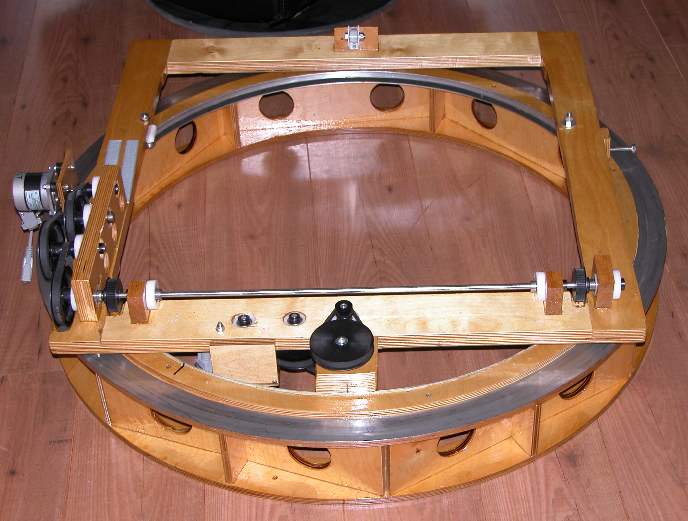
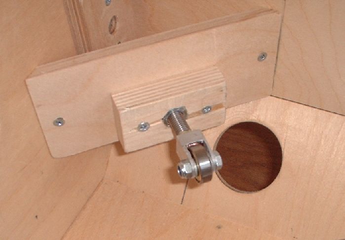
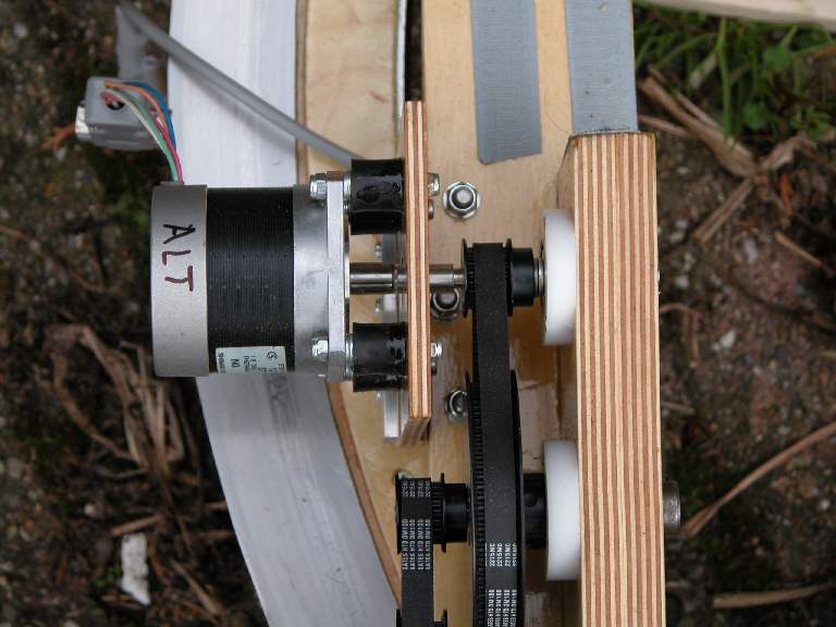
The groundring, pictured above, is made of 12 mm thickness Baltic birch plywood. The width of the ring is 75 mm. The stainless steel, 1 mm thick ring on which the azimuth roller bearings ride, is 45 mm wide. The inside diameter of the ring is about 815 mm diameter and the outside diameter about 965 mm. The height of the supports between the upper and lower ring is 100 mm. The total weight of the ground ring is 7.9 kilo's. In this picture is shown how I mounted an aluminium bearing ring inside the upper ring of the groundring. The black ring on the aluminium inner ring is the belt for the azimuth drive. Look here for a close-up. It is glued to the aluminium with bison kit contact glue. The 8 mm diameter stainless steel altitude drive shaft (picture above) drives both altitude bearings . It runs through four (white) delrin bearing blocks, with two rollerskate bearings each. I assembled the shaft, all of the bearings and wheels and the wooden support blocks (including the left one with the holes for the altitude drive), before glueing the support blocks to the flexrocker. This made it easy to keep everything aligned. |
|
|
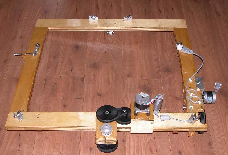
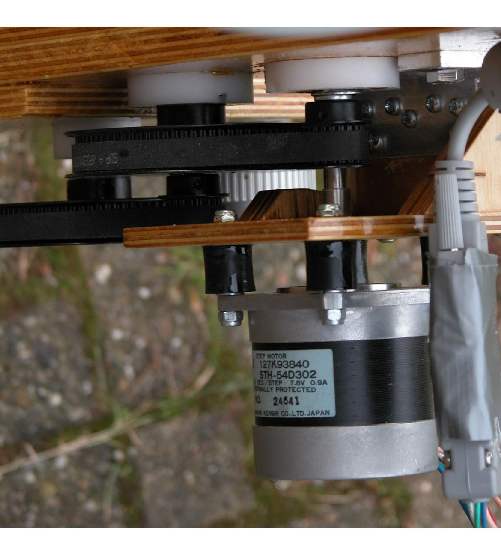
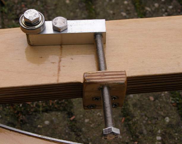
And this is how the flexrocker looks from below, motors and cabels installed. The motors are mounted on wood, with rubber dampers between the wood and the motor. The motors are, as already mentioned above, connected to the shaft of a the first pulley of the reduction system, with a piece of rubber fuel hose. Here is apicture of the altitude drive plus motors and here is the same for the azimuth drive. One lesson learned (the hard way) about the flexible rubber couplings: they tend to harden when getting older and lose grip on the shaft, resulting in slippage. So, if you use those couplings and observe far away from home: be sure to take some spare couplings with you and tools to mount them to your drive. In the two lower corners of the flexrocker and on the back side, the four azimuth bearings can be seen. They are made of one rollerskate bearing ach, mounted in a piece of aluminium U-profile. The bearings ride on the top ring of the groudring, on a ring of 1 mm thickness stainless steel. The stainless could be cut easily with a jigsaw, using lots of cutting oil. Without cutting oil the saw was already useless after sawing an inch or two. To keep the rocker centered, two rollerskate bearings ride against the aluminium ring on the inside of the upper ring of the groundring, while the cogwheel of the drive is engaged with the belt, which is glued to the aluminium ring. One of the bearings, the one to the left on the picture above, is adjustable. Look here for a close-up.
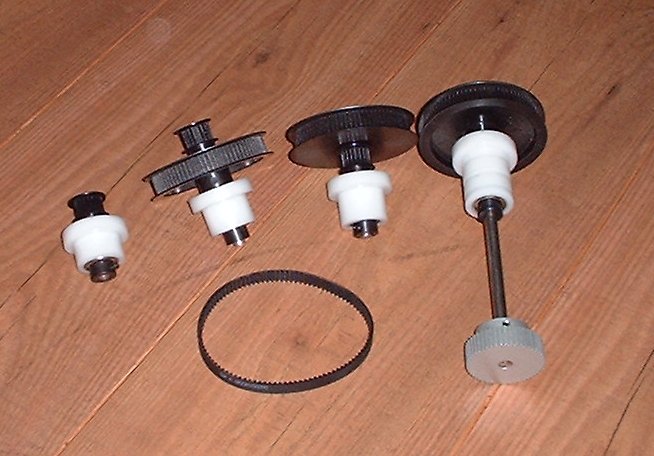
Go-to and tracking: Mel Bartels' stepper systemThe two pictures above show both drives. The small pulley's have 20 grooves the large have 80. The timing belts driving the pulley's have 100 grooves. I use 9 mm wide, 3mm pitch HTD belts. The pulley's are made of plastic, with an aluminium insert. The shafts go through two rollerblade bearings each. The bearings fit tightly into the white Delrin bearing blocks shown here . |
|
|
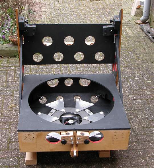
Above is a back view of the finished mirrorbox. Visible are the rollerbearing lateral supports, the 18 points cell and the six splitblox for mounting the trusses. Also visible is one of the four four corner braces. They are glued to the walls to make the mirrorbox stiff. The 9 mm thickness top baffle is glued to the sides of the box and to the cornerbraces. The 80 mm diameter fan blowing to the back of the mirror is visible below the mirror cell. In the two large holes and the small hole in between at the front of the mirror box, three fans (two 80 mm and one 60 mm diameter) will be mounted, for blowing across the mirror face . The photograph below shows a close-up of one of the roller bearing edge supports. Look here for information for how I made them.
|
|
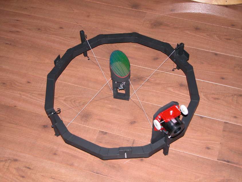
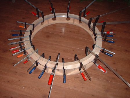
| Originally, I made a three-vane spider, using 0.3 mm thickness wire. But that was not good enough to prevent the secondary from moving when going from zenit to horizon, causing the system to go out of collimation. So, thinking the cause might be the three vane spider and the thin wire, I made a four-vane spider, using 0.5 mm thickness wire. The original aluminium ring however, made of 20 mm diameter square aluminium tubing (bent into a ring as described here), turned out to be too flexible and the collimation problem, although not as large as before, persisted. Therefore I made another ring, from 30 mm tubing. I couldn't bend that one into a ring, reason why I made the twelve-angle polygone, shown in the picture above. I keeps it's collimation very well now and all this work made me an experienced wire spider builder. The four-vane wire spider is made of 0.5 mm (0.02") thickness metal cable. I used two length's of wire. I used a jig (see these pictures) for the wiring, which makes it a very easy, ten minute job, once the jig is in place. When the small pieces of metal on the jig are taken away, the jig can be taken off the ring in four parts. The total weight of the assembly, including the focuser and the secondary, is 2.5 kilo's (5.5 lbs). The minimum inside diameter of the polygone is 560 mm . I made the 140 mm high, 67 mm wide secondary hub from pieces of 20 mm diameter aluminium tubing, (4x67 mm length, 6x10 mm length), glued together. |
|
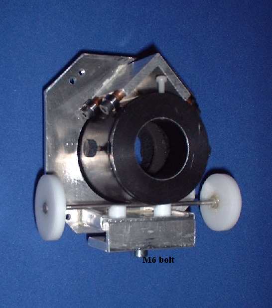
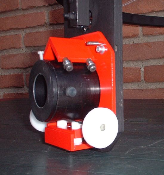
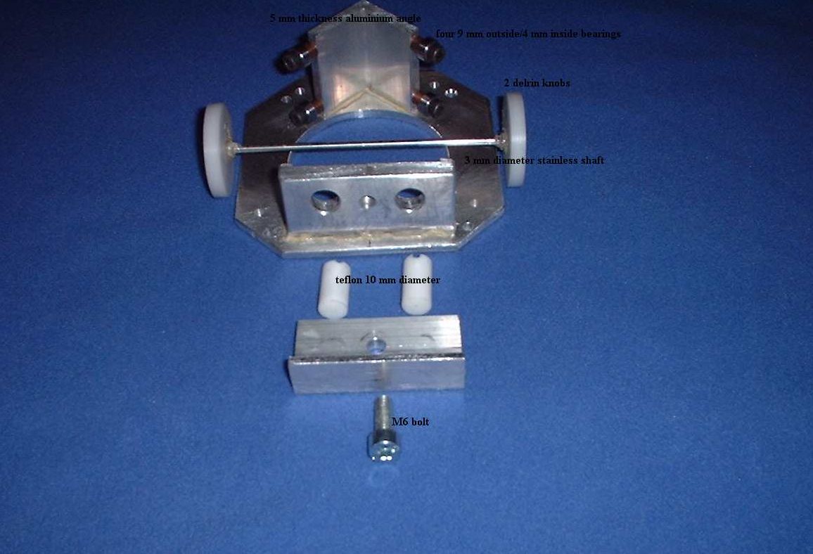
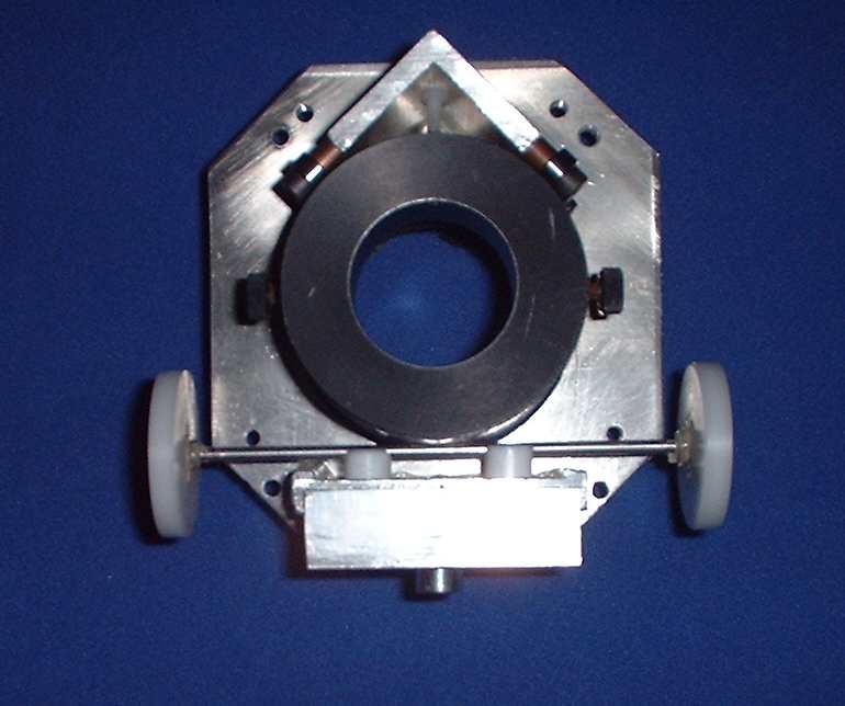
| The selfbuilt Crayford focuser is made of aluminium. The mounting plate is 4 mm thick. By turning the M6 bolt at the bottom of the picture, two 10 mm thickness pieces of teflon are pushed upward against the 3 mm thickness stainless steel shaft. Movement of the drawtube is very smooth. See this picture for a closer look at the parts and this picture for a front view of the focuser. The price: about $40.-, considerably less then the price of a commercial one. Total weight of the focuser is 0.365 kilo's (0.8 lbs). I didn't invent the design myself. It's a combination of ideas I found on the internet. See my linkspage for all selfmade Crayfords I found. Below is a picture of the painted focuser, mounted on the secondary ring. In reality, the color is more red and less orange. |
|
|
Go to: main menu
Go to: A 20 inch f/3.6 computerized Dobsonian
Go to: Building a trilateral computerized 20 inch f/5 Dobsonian Email to: Jan van Gastel |