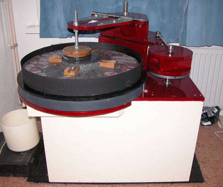
Making a Mirror-O-Matic Mirror Making Machine
 M-O-M 20, good for mirrors up to 20 inch diameter |
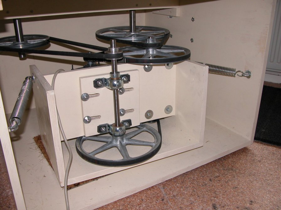
Detailed plans and a hardware kitAfter having made five mirrors by hand, I decided to build a mirror making machine. I did a google search and arrived soon on Dennis Rech's 'Mirror-O-Matic' pages. Just what I was looking for! Once I had seen a grinding machine, working at 380 Volts and weighting about 300 kilo's, but this one looked quite different: lightweight, very compact and working on normal household volts. I tried to find parts in Europe, but after one week of googeling, I didn't even find a suitable motor. So I contacted Dennis and he sent me the metal hardware kit for the '20' version of the machine, capable of making 20 inch mirrors, and a CD with building plans. The building plans are very clear, complete and detailed, which makes building the machine not very difficult. Just follow the plans and you're good. The wood I used is all 18 mm Baltic birch plywood. The turntable is made of two 18 mm layers, glued together. The red finish is a two component polyurethaan paint. I finished the 'M-O-M 20' in July 2011.I use the M-o-M for all stages of the mirror making process, so also for figuring. For figuring I use the 'Zambuto method'. Some years ago Carl Zambuto made very detailed examples of his figuring method, for an 8", a 10" and a 12" mirror. The .pdf files of the examples can be found in the files section of the Zambuto mirror yahoogroup. Much of his advise, often as answers to questions of ATM, can also be found in the archives of the group. The powerheadThe powerhead - motor and two shafts plus pulley's - is pictured below. The motor I use is a 1/2 HP Dutchi 3-phase, 1440 rpm motor, running at 400 volts. I also bought a variable frequency drive (VFD), giving me the possibility for ramp up and ramp down. With the motor running at its nominal speed, the shaft next to the motor - only the 10" pulley on it can be seen - runs at 213 rpm and the other shaft, visible on the front side of the photo, at 32 rpm. By changing pulleys on these two shafts the speed of the turntable (shaft and pulley in the right corner) and the excenter (left corner) can be adjusted. And of course the VFD gives me the possibility to get any speed I can't get using the pulley's alone.
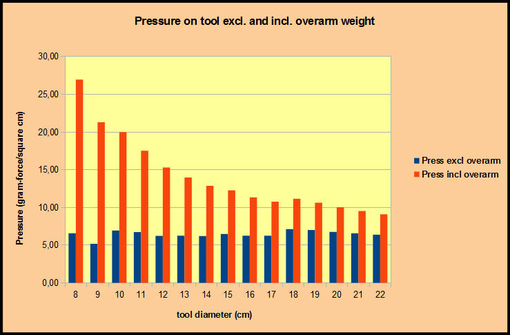
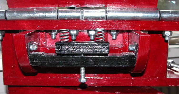
Reducing the overarm weightThe overarm of my M-o-M (including the center pin) weights 1025 grams (2.26Lbs). It's clear that this weight adds to the pressure of the tool (pitch lap) on the mirror. This can be a problem while figuring, especially with smaller tools. In the table below the pressure in gram-force per square centimeter (divide by 70.2 to get PSI) of my tools is shown, with and without inclusion of the overarm weight.
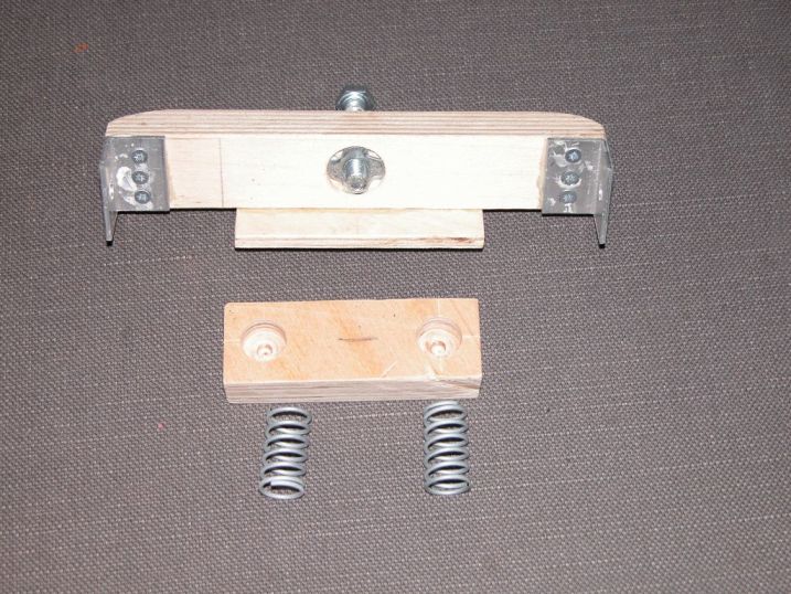
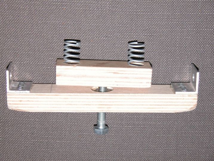
The pressure per tool without the overarm weight doesn't differ much, but when including the overarm weight, the pressure of smaller tools on the mirror becomes progressively larger. For example, the pressure of the 22 cm diameter tool plus overarm is 1.42 times the pressure without it, for the 8 cm tool the ratio is 4.1! To be able to control the pressure I made a simple 'overarm lifter', with two springs. By turning an M8 bolt I can compress the springs against the overarm, lessening the pressure of the overarm on the tool. The springs I use are 27 mm long and 15 mm wide (outside diameter). Max. force of each spring is about 64 N, with a spring constant of about 3.8 N. The springs push agains the overarm at 40 mm distance from the hinge, where the downward pressure of the tool is 91 N, so both springs together are strong enough even too take all of the overarm weight away from the tool. Below are photographs of the parts of the overarm lifter, disassembled and assembled and a photograph of the instrument installed in the M-o-M. I drilled a 10 mm hole in the bottom of the piece of wood carrying the springs and pushed a piece of 8 mm inside diameter messing tubing into it, to let the bolt turn easily and prevent the piece of wood from slipping off.
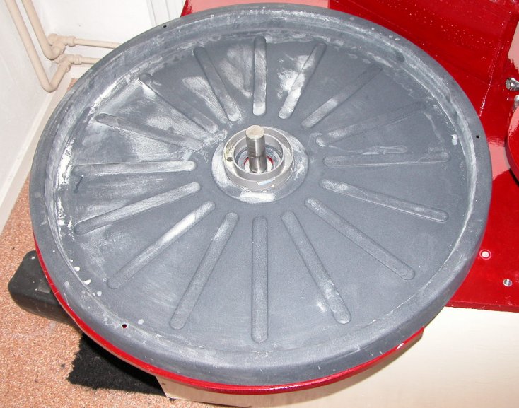
The drip panThe drip pan (photo below) under the turntable is a 650 mm diameter flowerpot saucer. Because it is too shallow (the turntable throws slurry over its edge) I made a kydex ring, glued to the inner side of a wooden ring. Three bolts through the wooden ring fit into the three holes visible in the rim of the saucer, making the ring easily removable from the drip pan. The saucer is made of polypropyleen, which cannot easily be glued and I had to glue a piece of pvc pipe in it's center, around a hole fitting over the turntable shaft. Berthold Hamburger pointed me to a loctide product, which I did use. It is a combination of a polyolefin primer, loctite 770 and a glue, loctite 406. It worked very well. The small hole to the left of the shaft, between the two pvc rings, is the water outlet.
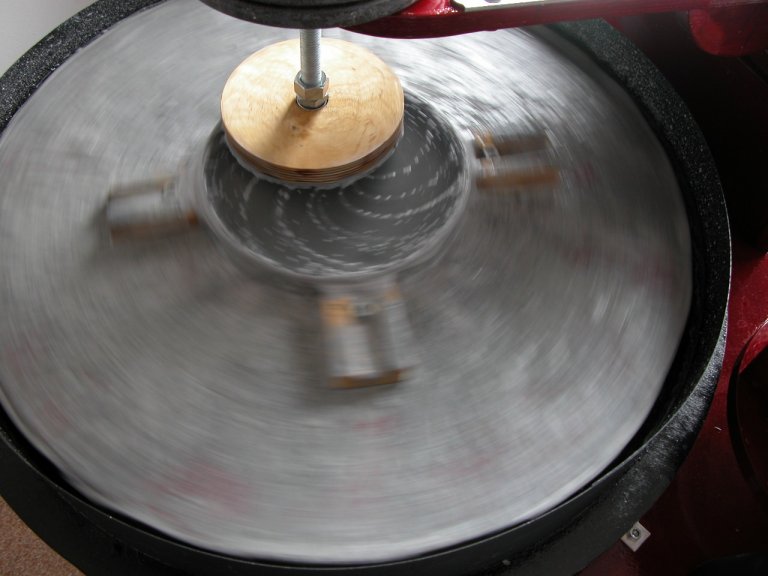
GrindingOn the picture below the machine is fine grinding an 8 inch mirror with an 71% tool (143 mm diameter) and 9 micron aluminium oxyde. The bent lines on the mirror are the effect of the tool turning - with respect to the mirror - faster at the central part of the mirror as compared to the edge zones. The speed of the turntable is 45 rpm here, but I use speeds up to 80, sometimes even 100 rpm for fine grinding regularly.
Polishing and parabolizingAfter fine grinding with 3 micron aluminum oxide I start polishing using a turntable speed between 60 and 100 rpm. Polishing then takes only 2.5-3 hours. For figuring I also use the M-o-M exclusively. I use the 'Zambuto method'. The turntable speed is about 5 rpm and the overarm moves the tool across the mirror 40-50 times per minute, depending on the mirror diameter. |
|
|
Go to: main menu
Go to: A 20 inch f/3.6 computerized Dobsonian
Go to: Building a trilateral computerized 20 inch f/5 Dobsonian Email to: Jan van Gastel |