Building and using a Bath interferometer
 |  | 
|
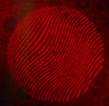
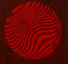
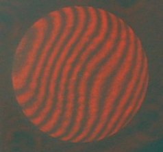
To be able to measure the quality of a mirror using more then one test (Foucault test), I made a Bath interferometer. There's lots of information on the internet, mostly gathered and/or written by members of the bath interferometer group at groups.io. Most of the information one needs can be found in the wiki of the group.
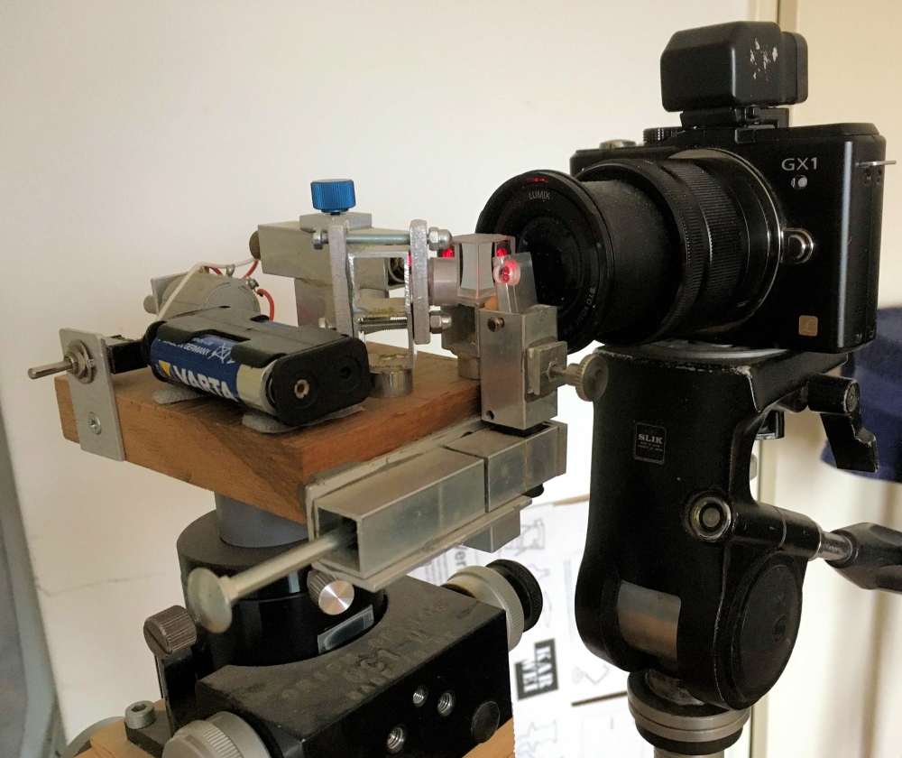
Is it difficult to build one?Building a Bath interferometer is not very difficult, but it is important to take good notice of what's written in the wiki and elswhere about the optimal size and optimal placement of the parts relative to each other and about the requirements for the parts to be able to move in X (left/right), Y (up/down), and/or Z (closer/further away) direction, before starting to build. AND....there's more then only building the interferometer. It's not trivial to make contrasty and well shaped interferograms, using a webcam or a photocamera. And outlining the mirror in the software needs to be done very accurately - at the pixel level - to get reliable results. Below is a photograph of the setup I use at the moment. Further down this page is a picture showing a webcam instead of the camera, this was my first setup. Drawback of the webcam was, that I had to make lenses myself and that a lens was only good for only a very small range of F/values. With this camera plus zoom lens I can test every mirror I want. Positioning the camera when setting up to test a mirror, is a matter of minutes. |
|
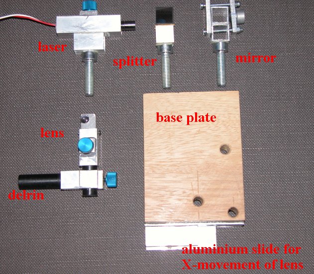
Optical partsThe only optical parts to be used are a laser (I have a red one), a small 50/50 beam splitter, a small biconvex lens and a small flat mirror, which I all purchased from Surplus Shed. There's no need to use high quality, expensive optical parts because of the 'common path' design (see literature). Dimensions of the parts I used: beam splitter 15x15x15 mm, BCX lens 6 mm diameter f/0.67, flat mirror 12.4 mm diameter and 6.2 mm thickness (my 20 inch mirror would be 10 inch thick if it had the same diameter/thickness ratio). The distance between the two beams - should best be kept within 8 millimeters - is 6.25 millimeters. I can dim the laser with a 1000 ohm potmeter (see 'view from above' picture, below). For the layout drawing of my interferometer click heremountingsI made the mountings from square 15x15 mm aluminium tubing, to which I glued an M8 bolt to mount the parts on the 103x78 millimeters (hard) wooden base plate. The mirror, lens and beam splitter are glued to their aluminium mounts with 1 mm thicksilicone adhesive. To be able to move the lens in X and Y directions I used delrin, sliding smoothly -without having room to make unwanted movements - in and out the aluminium tubing. Aluminium parts were glued together and to the wood with a two component metal epoxy. The blue knobs are in the pictures are fastening knobs, except for the one just below the lens, which is meant to rotate the lens a little around the X-axis.
|
|
Movements of the parts:1. The beam splitter can only rotate around the Y-axis.2. The laser can rotate around the Y-axis and around its own longitudinal axis and can be moved in the Z direction. 3. The mirror can rotate around the Y-axis and (a little) around the X-axis, to be able to align the beam reflected by it. 4. The lens can be moved about 15 millimeters in X (left/right) and about 10 millimeters in Y direction (up/down), can also be rotated a little around its X- and Y-axis, to place it parallel to the beam splitter (after I made this part I learned this wasn't necessary) and can be placed at 2, 9.5, 11 and 15 mm distance from the splitter. It's at 9.5 mm now and as far as I can see, that's fine.
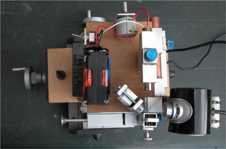
View from aboveOn the picture below- I used a webcam instaed of a camera in the beginning - the Bath interferometer is shown from above. On the left side and upper side the handles of the XZ-stage can be seen. To move in verical (Y) direction the interfereometer is mounted on an old focuser on top of the XZ-stage. The XYZ-table is relatively heavy, but this has the advantage of being very stable and not having to be very cautious when switching the interferometer on/off or manipulating the direction controls. |
|
Using the Bath and the DFTFringe free softwareFor more information about the bath interferometer and how to use it, see: Bath interferometer by Georg Roberts, There are links to informative youtube videos on this page.A video about setting up the Bath interferometer to test a mirror, by Dale Eason, can be found here: Setting up a Bath interferometer to test a mirror My video about parabolizing a mirror, using the Bath in the last stages of figuring: Parabolizing using the Bath interferometer (using the Bath starts at time 9:50)
DFTFringe is a very powerfull program for analyzing the interferograms you take with your self built interferometer. It is freeware and very well maintained. These video's are good places to start using this excellent software: DFTFringe quickstart by Dale Eason, author of DFTFringe
|