
| The platform for my 12 inch scope (link to detailed building
plans at the end of this page) has eight bearings: four at the south
side and four at the north side. The platform I built for my 20 incher
only has five: four at the north side: two tangent and two thrust
bearings and only one thrust bearing at the south side. To prevent the
platform from slipping off the north thrust bearings, I made a buffer.
It is less then a millimeter away from the aluminium rim of the south
sector and is not in touch with this sector during normal movement.
This buffer is the only reason an accurately made sector at the south
side is needed.
Other differences between this platform and the 12 incher platform are:
1. A tangent arm drive instead of a roller drive. 2. A DC motor instead of a stepper motor. I had vibration problems with the stepper. The DC motor is accurate enough for visual use and does not cause vibrations. A good alternative would be a stepper with Nils Olof Carlins stepper driver. But it is too difficult for me to build. To calculate the dimensions of the platform, I used the same program I wrote to design the platform for my 12 inch scope. The program can be found at this page. If you prefer a spreadsheet, click here. The spreadsheet will give more degrees of freedom in constructing the platform. |
| |
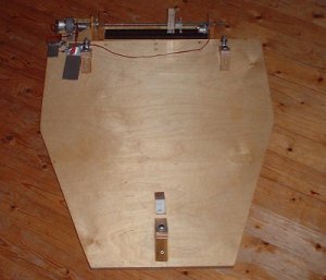
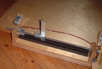
Overview of the platform, as seen from the south side. As a
center pin
I use a piece of 20 mm diameter aluminium tubing. The lead for the two
fans goes through this pin. For smooth movement I use a central teflon
pad, one mm thicker then the other three pads. The platform is made of
30 mm thick baltic birch. |
 |
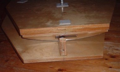
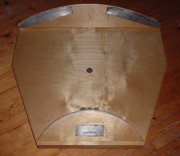
The baseboard is made of 18 mm thick baltic birch. There are
three
"bearing blocks": two at the north and one at the south side. The
buffer behind the south block is lined with teflon. This buffer is
absolutely necessary. Before I made it, the scope has slipped off the
bearings twice, when I made a sudden, badly coordinated movement and it
was not easy to get the fully assembled telescope back on the bearings
again. |
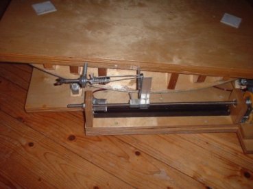 |
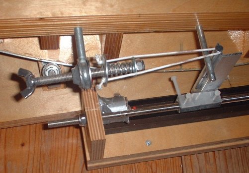
The north side of the platform with the threaded rod and the spring construction to hold the drive-arm firmly against the aluminium angle (being moved from West to East by the threaded rod) to prevent play. The tension of the spring can be adjusted by turning the wingnut. A close-up of the spring construction can be seen here. |
 |
The south side of the platform with only one bearing. I used a thrust bearing. At lower lattitudes (I live at about 52 degrees North) a tangent bearing might be a better option. |
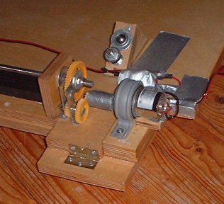 |
The 12 V DC motor. The DC motor has a built in 200:1 gear, reducing the speed to 31 rpm. To reduce the speed further I have built an additional reduction of 7.5:1, reducing the speed to 4.13 rpm. With a PWM controller circuit the speed of the threaded rod is further reduced to the 2.8 rpm needed for tracking at the right speed. |
 |
The 8 mm diameter threaded runs through two couplers (glued together). A piece of aluminium angle, which is glued to the couplers, pushes against the drive-arm to move the platform from West to East. To reduce the play four 3 mm diameter plastic bolts are used. |
 |
A close up of the piece of aluminium angle, three of the four plastic bolts mentioned above and one of the north bearing blocks. The red dot to the right is the switch to stop the motor when the platform has reached its most easterly position. |
 |
The two sectors are lined with two mm thick metal sheet, where in touch with the ball-bearing type thrust bearings. The sectors are made of 18 mm thick baltic birch. |
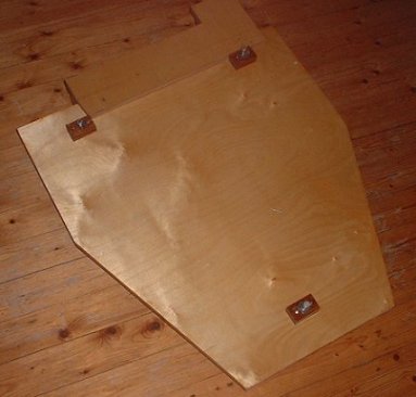 |
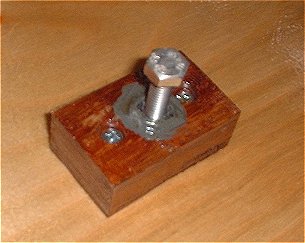
The "feet" of the platvorm. In wooden blocks couplers are glued with metal epoxy. In the couplers M8 bolts are mounted. By turning these bolts out or in the platform can be leveled. The difference between a bolt fully turned in and a fully turned out is about 1 inch. A close-up of one of the three feet can be found here. |
| Go to: main menu Go to: platform building plans |