A mirror is supported by an n-point mirrorcell (18 points in
my case). But the mirror only seldom rests with its total weight on all
18 points: only when pointed at the zenith. When the mirror is glued to
the cell with RTV it hangs most of the time on the RTV blobs with part
of its weight. Using a sling, it rests most of the time with a part of
its weight in the sling. At first I had my mirror glued the cell with
silicone RTV. The result was not what I wanted: in the startest I saw
astigmatism (don't know if it was caused by the RTV). To make sure if
the astigmatism is in the glass or not, it is necessary to be able to
rotate the mirror. If the astigmatism follows the position of the
mirror: the cause is in the glass. Rotating can't be done when the
mirror is RTV-ed to the cell. So I cut it loose with a 0.24 mm
thickness guitar wire (which was very easy). Next solution I tried was
a "traditional" 2 inch wide car safety belt sling. This had at least
four drawbacks:
|
| |
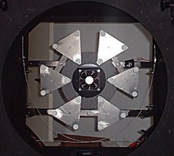
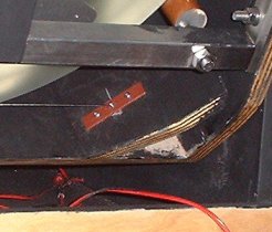
A double sling, as shown in the picture to the left, is a combination of two slings: one starting at the right side of the mirror, running under the lower edge (assuming the telescope points to the horizon) to the right side of the mirrorbox. The other one runs from the left side of the mirror to the right side of the mirrorbox, crossing the first one at the midpoint of the lower edge of the mirror. Below the mirror the slings are fastened immovable (against the corner braces) with a metal plate screwed over a 16 mm wide hole, which holds the locker of the cable. At the other end (next to the mirror) both cables are adjustable. Both cables need to be adjustable to be able to get the mirror positioned at the exact center of the mirrorbox, relative to all four sides of the mirrorbox. It is also possible that the (new) cables will stretch a little in the beginning, which makes adjusting necessary as well. All four attachment points of the cables have to be at the height of the middle of the width of the mirror. This way the two cables will run exactly over the middle of the mirror's edge. |
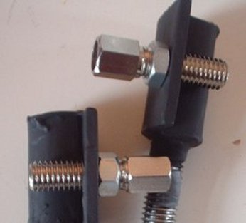 |
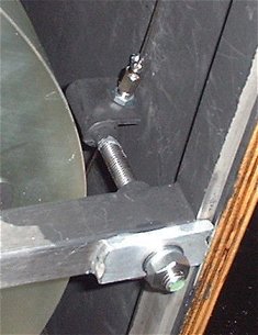
To the left is a
picture of the adjusting mechanism (and here's one in action). It
consists of two pieces of 10 mm thickness stainless steel threaded rod,
glued to a part of a hinge
with two component metal epoxy. Staying in the world of bicycles for a
while: the other part of the mechanism is the adjusting mechanism of a
bicycle break. It works perfectly!
After the cables and the adjusting mechanism are installed and the
mirror rests on the suport points again, the adjustmentproces can
start. The raw adjustment is best done from above, with the mirror
resting with its total weight on the support points. Don't drop a screw
driver or big sweat drops on the mirror! When the position of the
mirror is about right, the mirrorbox is tilted to put most of the
weight of the mirror in the slings. The rest of the work is done from
the backside of the mirror, gently turning the adjusting bolts. With a
piece of metal or wood cut to the right lenght, the distance from the
mirror to all four sides of the mirrorbox is measured repeately, until
the mirror is positioned at the exact center of the mirrorbox.
|
|
Go to: main menu
Go to: the mirror cell
Go to: secondary and spider
Go to: the truss construction
Go to: the double sling Email: Jan vanGastel |