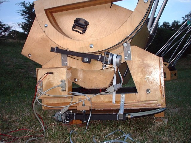
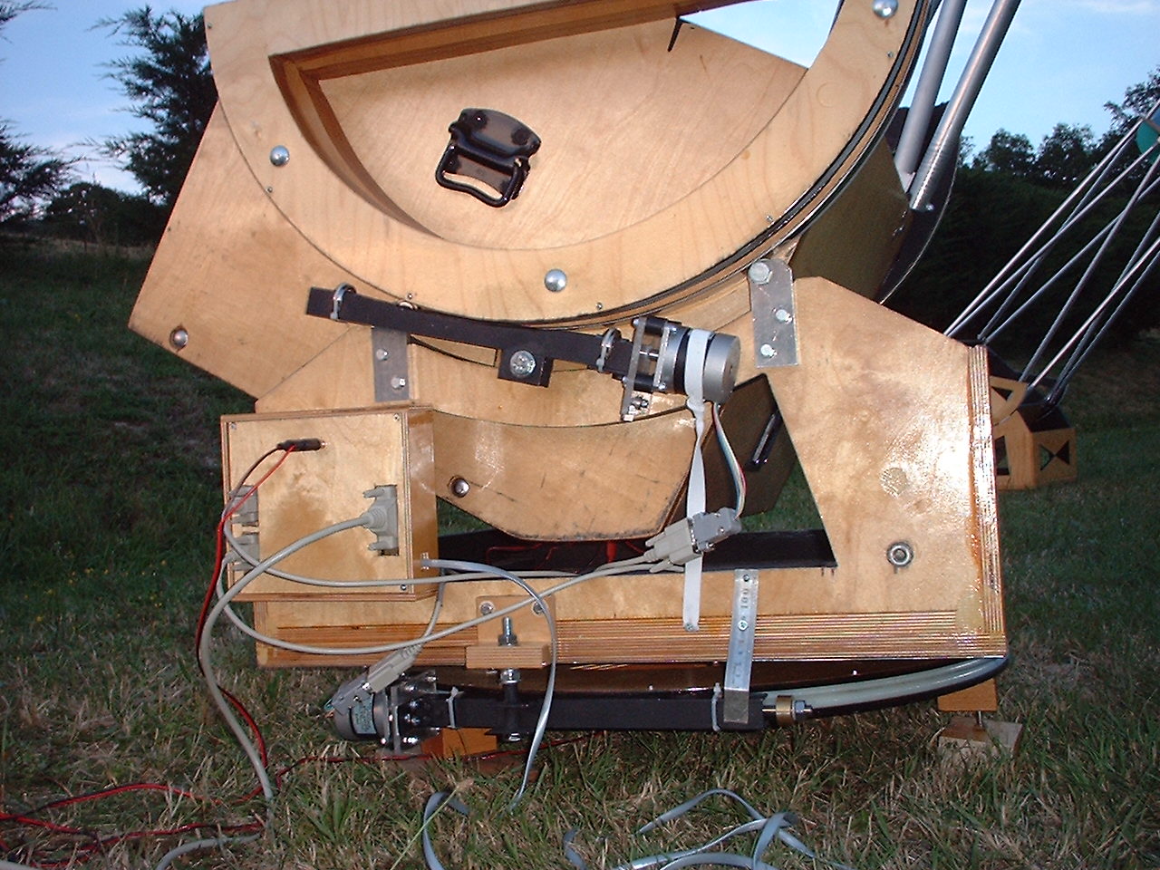
As shown in the picture bove, the drive systems consists of
wormwheels and worms on altitude and azimuth axis. The wormwheels are
made of engaging nylon threaded rods (Rex Kindell's method, see
linkspage) of 10 millimeter diameter. Reduction is 1434:1 for the
azimuth and a bit less for the altitude drive. Using 40 microsteps,
gives a microstep size of about 0.11 arcseconds. How I tuned the 40 microsteps can be found here and how I calculated the fullstep size can be found here.
Against the rocker bottom I screwed a 1 mm thick metal plate.
The rocker runs on three roller assemblies of two rollerskate-type
bearings each. The altitude bearings, lined with 0.5 mm thick stainless
strips, run on two of these bearings, mounted (one-sided) on a 6 mm
thick aluminium bar.
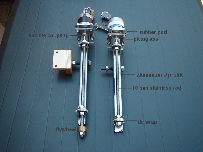
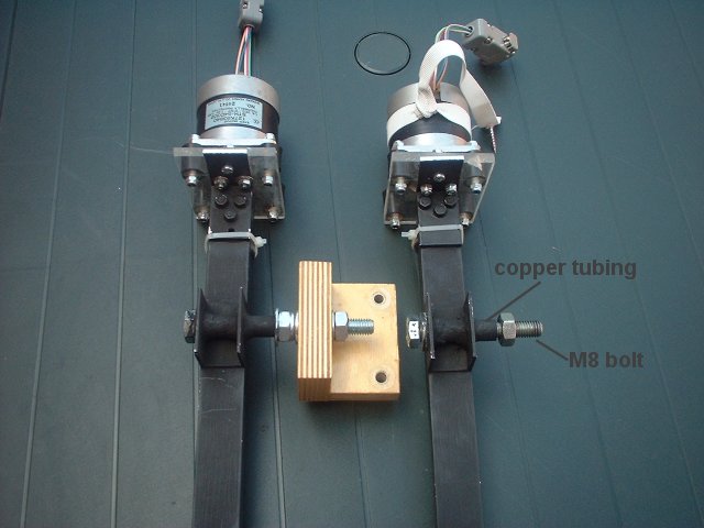
Mounting the stepper motors
To mount the motors and worms, I used Dale Eason's method
(link on linkspage). The motors are attached to the worms as shown on
the picture below. Both motor-worm combinations pivot around a 8 mm
bolt. The azimuth worm is 'pressed' against the wormwheel with a piece
of an old metal ruler, the altitude motor with a piece of elastic band.
The azimuth worm has a small flywheel. Each worm runs through two
'rollerskate-type' bearings. The bearings are mounted in slots in
aluminium U-profile and locked with a bolt on each side. A tie-wrap
prevents the bearings from coming out of the slot. The motors are
attached to a plexiglass mounting plate with anti-vibration rubbers.
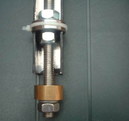
The motor axes are connected to the threaded rods with flexible rubber
(fuel hose) couplings. Click here to see the
back of the assembly and here
for a detail of a bearing and flywheel.
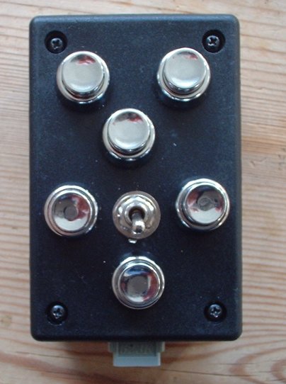
The switches of my handpad didn't work well. The problem came
up after having used the handpad for about half a year. I had to push
some switches (not always the same one) several times to let them respond.
After having used the handpad about a year and a half it often took a
minute or (much) longer before a switch responded. That's when I
decided to mount new switches, as shown in the picture below. The new
ones are a bit thicker (9.5 mm instead of the 7 mm of the original
ones) and I had to make the holes a bit wider, but they fit into the
box nicely.
|
