Motorizing a 12 inch Dobsonian telescope

Celano Controller

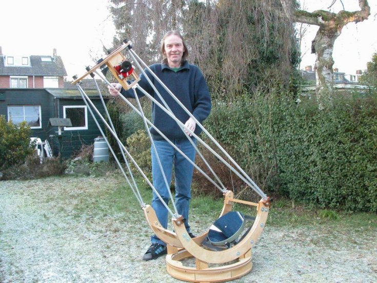
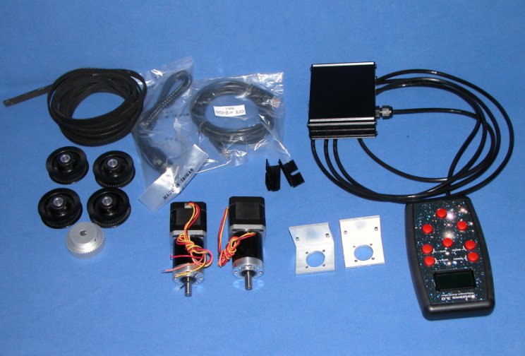
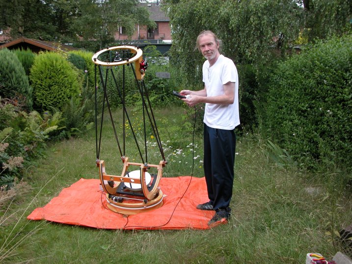
Some years ago I built five 12 inch telescopes (see five 12 inchers). One of those telescopes was for my friend Willem, pictured below with his telescope. After a couple of years of starhopping 'fun', Willem told me he liked observing objects much more then finding them and we decided to motorize his telescope. We decided to do this with the 'Celano Telescope Controller', sold by the Dutch internet shop 'Deepskyparts'. I have seen an older version of this system in action before and was really impressed. And recently Carl Vehmeijer, one of the owners of Deepskyparts, redesigned the computer and handpad, making them much smaller, easy to handle and very good looking. Deepskyparts also sells quality stepper motors, pulley's and timing belts, so all motorizing hardware can, very conveniently, be purchased from the same source.
Willem and his hand controlled telescope

The hardware

The teflon pads for the azimuth drive were replaced by rollerskate bearings. The new azimuth ring is made of 18 mm instead of 9 mm thickness plywood and is redesigned to fit the motors and the altitude and azimuth shafts. Just like my 20 inch f/3.6 scope, this telescope is driven by belt/pulley drives to move in altitude and azimuth. Below a picture of all the parts I purchased from Deepskyparts.

Calculating the reduction

The motors are geared to a 71.3:1 reduction. Combined with the reduction accomplished with the timing belts - 1:21.9 and 1:16.4 for Az and Alt drive respectively - and dividing the 1.8 fullstep of the steppers into 40 microsteps, the reduction results in a microstrep size of around 0.10 arcseconds for the Az-drive and 0.13 arcseconds for the Alt-drive. The reduction by the belts and pulley's can be calculated by counting teeth (or grooves) in the timing belts and pulley's, of bij dividing the diameter of the azimuth ring to which the belt is glued - and for the Az-drive the diameter of the circle where the bearings are cut from - by the pitch diameter of the drive pulley. When you don't know the diameter of the orginal circle from which the Alt-bearings are cut, there's an easy work around using the 'cosine rule', to be found here, and a spreadsheet to do the calculations is here.

Finetuning the reduction

After calculating the reduction by one of these methods, it can easily be finetuned bij using the 'rotated degrees azimuth' and 'rotated degrees altitude' buttons of the software. For the azimuth fintuning one only needs a laser taped to the flexrocker. Point it at a mark on a wall and move (using the direction buttons) the telescope 360° until the laser hits the wall at the same spot again. Click the 'rotated degrees azimuth' button, divide the number of 'degrees rotated' by 360 and multiply the result by the reduction found above. To finetune the altitude reduction, tape a leveler to the telescope and move the telescope up or down 90°. Divide the result (for instance the mean of 10 trials) by 90° and multiply by the above found altitude reduction, to find the correct reduction. Don't forget to save the new values and upload them to the motor. After uploading the software will startup again, set the readings back to zero and - if necessary - you're ready for another trial.

The drawing

My 'poor man's CAD drawing' of the flexrocker ring. I don't like to spend much time behind my desk to make drawings, so this it, except maybe for some small detail drawings if I need them. The Alt and Az motors, the Alt and Az drive shaft and bearings are all be mounted on this flexrocker.

The altitude drive

The altitude drive is made of two 48 grooves plastic pulley's (with aluminium insert), moving a timing belt on each of the rims of the altitude bearings. The stepper motor is connected to the 8 mm diameter stainless steel shaft with two 25 grooves pulley's and a small timing belt. All of the belts are 9 mm wide, 3 mm pitch HTD belts.

The altitude drive belt on the rim of the altitude bearings is shown below.

The azimuth drive

The azimuth drive consists of one 48 grooves metal pulley's running in a timing belt, glued to the white formica rim inside the base ring. The stepper motor is connected to the 8 mm diameter stainless steel drive shaft with a 25 grooves pulley (on the motor shaft) and a 48 grooves pulley (on the drive shaft) and a timing belt. The picture below is a close-up of the azimuth drive and on the second picture below the belt in the azimuth ring is shown.

The base ring, the flexrocker and the controller

Below is a picture of everything - except for the altitude bearings, truss assembly and secondary ring - assembled, including the controller. The controller is the black box on the left side on the flexrocker, the handpad is lying next to it. I tested today and everything works, motors move in the right direction and respond well to the press buttons of the handpad. The controller can be taken off the flexrocker by loosening only one bolt (by hand).

Under the flexrocker

Below is a picture of the flexrocker ring upside-down. You can see the four rollerbearings for moving in azimuth, placed under the altitude supports, the azimuth motor and the azimuth drive pulley. On the right side and left side - at 120° with respect to the azimuth drive pulley and each other - you see roller bearings to prevent the flexrocker from riding off the base ring. The bearing on the left side is pressed against the inner side of the ring with a spring. This spring should be strong. If not strong enough and especially if the telescope is not 100% level, the azimuth drive pulley will loose its grip on the teeth of the timing belt and the movement in azimuth will not be smooth any more and will stop eventually. With a strong enough spring, the scope doesn't even need to be level.

The completed telescope

Below is a again a picture of Willem, but this time with his motorized telescope. Everything works very well. Now we will have to wait for a clear night for first light and here in The Netherlands, you never know when that will happen.
Willem and his 'Celano controlled' telescope (same garden as top photo)

Go to: main menu

Go to: A 20 inch f/3.6 computerized Dobsonian Go to: Building a trilateral computerized 20 inch f/5 Dobsonian
Go to: Project: five 12 inch lightweight Dobsonians Go to: Motorizing a 12 inch lightweight Dobsonian
Go to: 20 inch telescope Go to: Equatorial platform Go to: Scotch mount Go to: Binocular mount Go to: Dobsonian tips
Go to: Bending aluminium Go to: Collimating Go to: Making a Krupa collimator Go to: Dotting the primary
Go to: A ballhead type telrad/finder mount Go to: Mirror making log of 300 mm mirror Go to: Astronomy
Go to: Using digital finder charts at the eyepiece Go to: Astronomy links Go to: Building a spherometer
Go to: Building a Bath interferometer Go to: A Foucault-Ronchi-Lyot tester Go to: Building a mirror making machine
Go to: Home

Email to: Jan van Gastel