Project: five lightweight 12 inch Dobsonian telescopes.
|
|
|
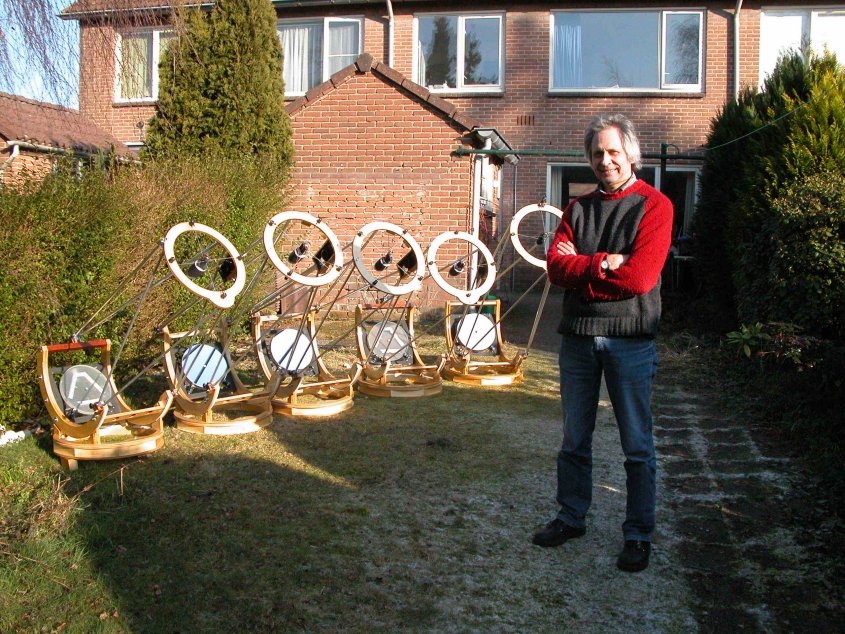
Why five?About two years ago, my girlfriend and I made two 12 inch mirrors. After the mirrors had been laying in a closet for more then a year, I decided to to build two lightweight telescopes for them. I already owned a 12 inch telescope, with a very good full thickness zerodur f/6.1 mirror and decided to make a lightweight 'house' for this one as well. I told this to my friend Willem, a base gitarist with whome I play the blues (on my harmonica) and he told me he was thinking about buying a 12 incher in the future. I thought well, if I can build three telescopes, I can build four, so I promised him to build one for him. Some time later a colleague and her husband visited me and, afer some talk about telescopes, well, I decided to make five. I started in Februari 2008 and now, Februari 2009, they are finished. Only the two mirrors for me and my girlfriend have to be aluminiumized. In the photograph above all five scopes are set up in my garden. From left to right: an f/5, two f/5.3 (Orion Optics mirrors), another f/5 and the f/6.1. The two f/5's differ only 2 mm in focal length, because maybe in the future I want to build a bino for them. The weight of the telescopes varies from 15 (f/5) to 19 (f/6.1) kilo's. Inspiration for the design was mostly Mel Bartels trilateral.
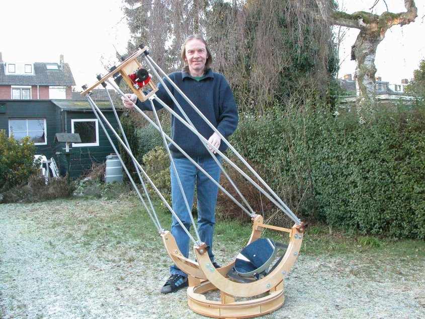
Eight and six tube systemsThe trusses of the two f/5's and the f/6.1 have 6 tubes, the trusses of the two f/5.3 scopes have eight tubes, because the new owners want to use a shroud. Below is one of the f/5.3 scopes, with his new owner, Willem. Summer 2012 I have motorized his telescope with the 'Celano controller'. If you like to see how it lookes now, please have a look at this webpage. |
|
|
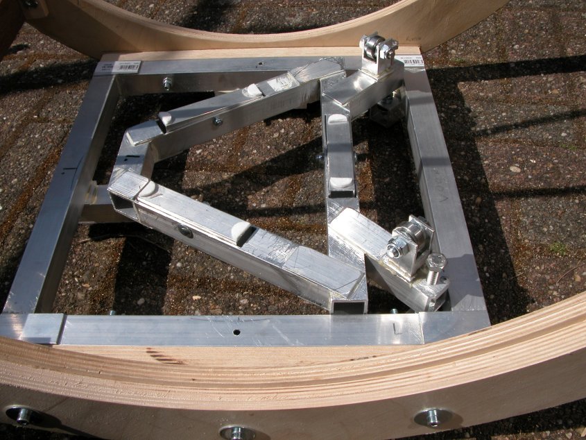
The eight-tube trusses and the front tubes of the six-tube trusses are connected to the end points of the altitude bearings. The tubes coming from the back of the six-tube truss scopes are connected to wooden bars between the altitude bearings. In a former 'prototype' I attached the front tubes and the tubes from the lower front to the back of the ring (six-tube truss) to the connecting bar between the two altitude bearings, but this is less stable, because that way, the trusses are longer and are less wide apart at the connection points. The front trusses are 12 mm diameter, 1 mm wall thickness aluminium. The longer trusses coming from the back side are 16 mm diameter. The flexrocker is a 9 mm thickness Baltic birch ring, with teflon pads sliding on the formica lined ground ring and riding on three rollerskate bearings against the inner rim of the upper ring of the ground ring. Setup time is about 3 minutes. |
|
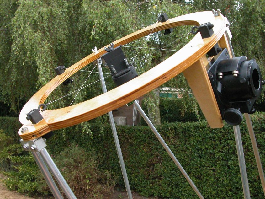
| I like making wire spiders, so I made one for these five 12 inchers as well. The wire I used is 0.5 mm thick metal cable, tensioned with simple eye bolts. The distance between the attachment points of the wire above and below the ring is 50 mm. The wooden ring is made of 12 mm thickness Baltic birch. The secondary hub is made of three pieces of 15 mm diameter square aluminium tubing and the secondary holder is made of 50 mm (for the f/6.1) and 60 mm (for the other scopes) diameter round aluminium tubing. The secondary is glued to the holder with three blobs of silicone adhesive. On the back of each secondary mirror I have glued an Astrosystems dew guard. Look here for some spider details. |
|
|
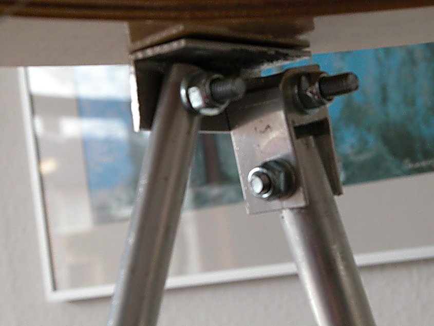
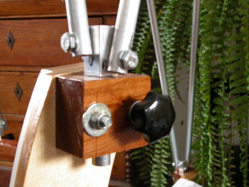
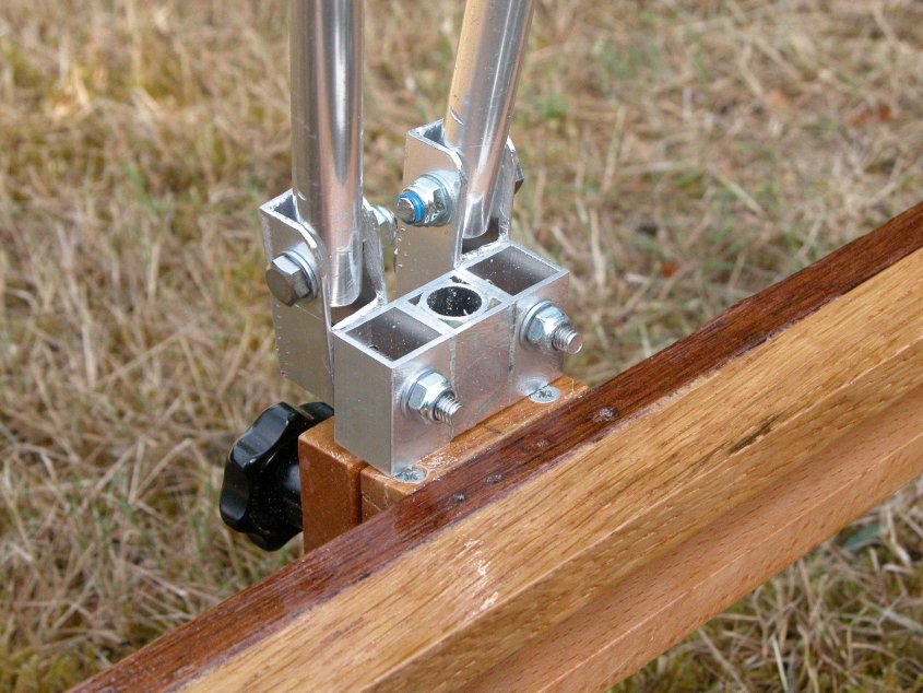
The trusses always stay connected to each other. To do that, I used a variation of Kurt Maurer's truss design, which I used a couple of years ago for my original 20 incher. To connect the back trusses of the six-tube telescopes to the ring and to give them the necessary freedom to move in two directions, I made a hinge as show in the picture above. The tube to the left only needs to move in one plane, the right one in two planes. The two pictures below show the splitblock and the way the trusses are connected to each other and to the lower end of the telescopes. The hinge in the lower photograph is only used in the six-tube trusses. To prevent the tubes from being squeezed, I put wooden dowels in the tube ends. |
|
|
|
| The mirror cell's are 6-point PLOP calculated cell's (deformation 1/809 lambda surface error), made from 25 mm diameter aluminium tubing, glued together with two component epoxy. The lateral supports are rollerskate-type bearings at 90 degrees from each other. Placement of the supports at the plane of the COG is calculated using Robert Houdart's program. Right in front of the supports are the collimation bolts: the primary can be collimated from above, at the front of the mirror. The third bolt is at the backside, below the cell. Using all three bolts the cell has a total travel of about 25 mm, to be able to compensate for eyepieces focusing further in or out then the focuser travel can account for. Look here for details about the collimation mechanism. |
|
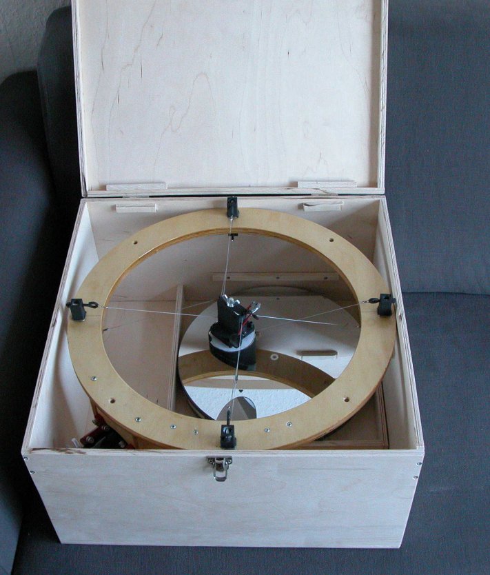
| For easy transport, the primary mirror and the secondary ring both fit into the box above. There's also a lid to protect the primary mirror, but I left it off to make the photograph. And there's plenty of room left in the box, to store other accessories. |
|
Go to: main menu
Go to: A 20 inch f/3.6 computerized Dobsonian
Go to: Building a trilateral computerized 20 inch f/5 Dobsonian Email to: Jan van Gastel |